SolarAir Can Controller Hardware


- Details
- Published on Sunday, 20 December 2015 17:02
- Hits: 7751
The electronic controller is made with a Raspberry PI, and some electronics on a PCB, and on top a Solid State Relais.
The Raspberry used is a version 2, but it should be exactly the samre with the version B(+) and it can probably be made with a version A as well. Now days the best and cheapest option is probably to use a Raspberry Zero, since it costs less then 10 dollar, and it uses the least power.
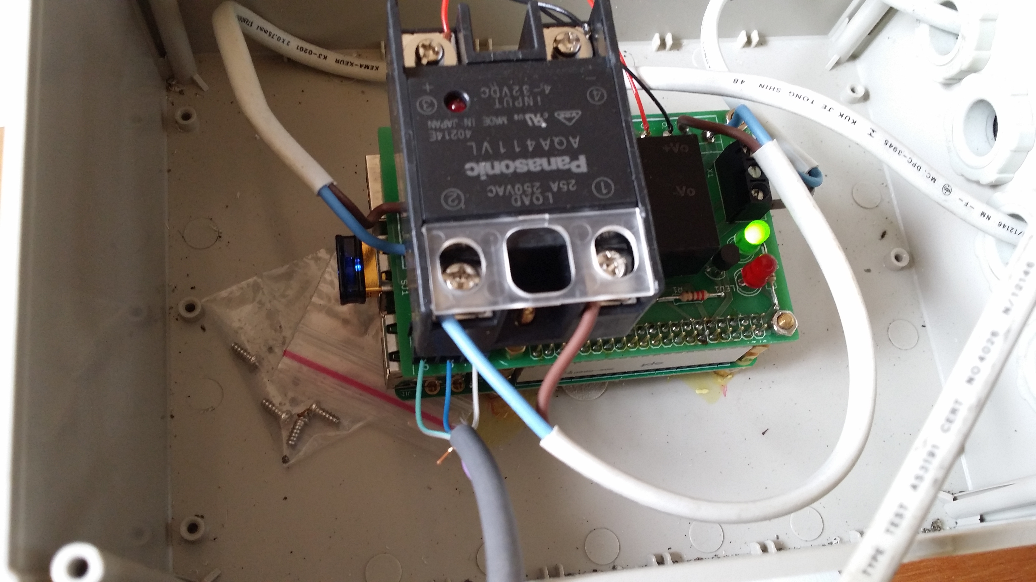
In the extra hardware is except some connectors and LED indicators mainly a AC to DC convertor to covert the power from the wall plug to a 5Vdc, and a solid state relais. The 5Vdc is not supplied to the raspberry in the typical way by means of the USB-port, but straight into the pins of the GPIO. The solid state relais used to power on the fan, is not soldered onto the PCB, but mounted on top by means of the screws.
A video explaining the hardware (except the temperature sensors!) is to be found here:
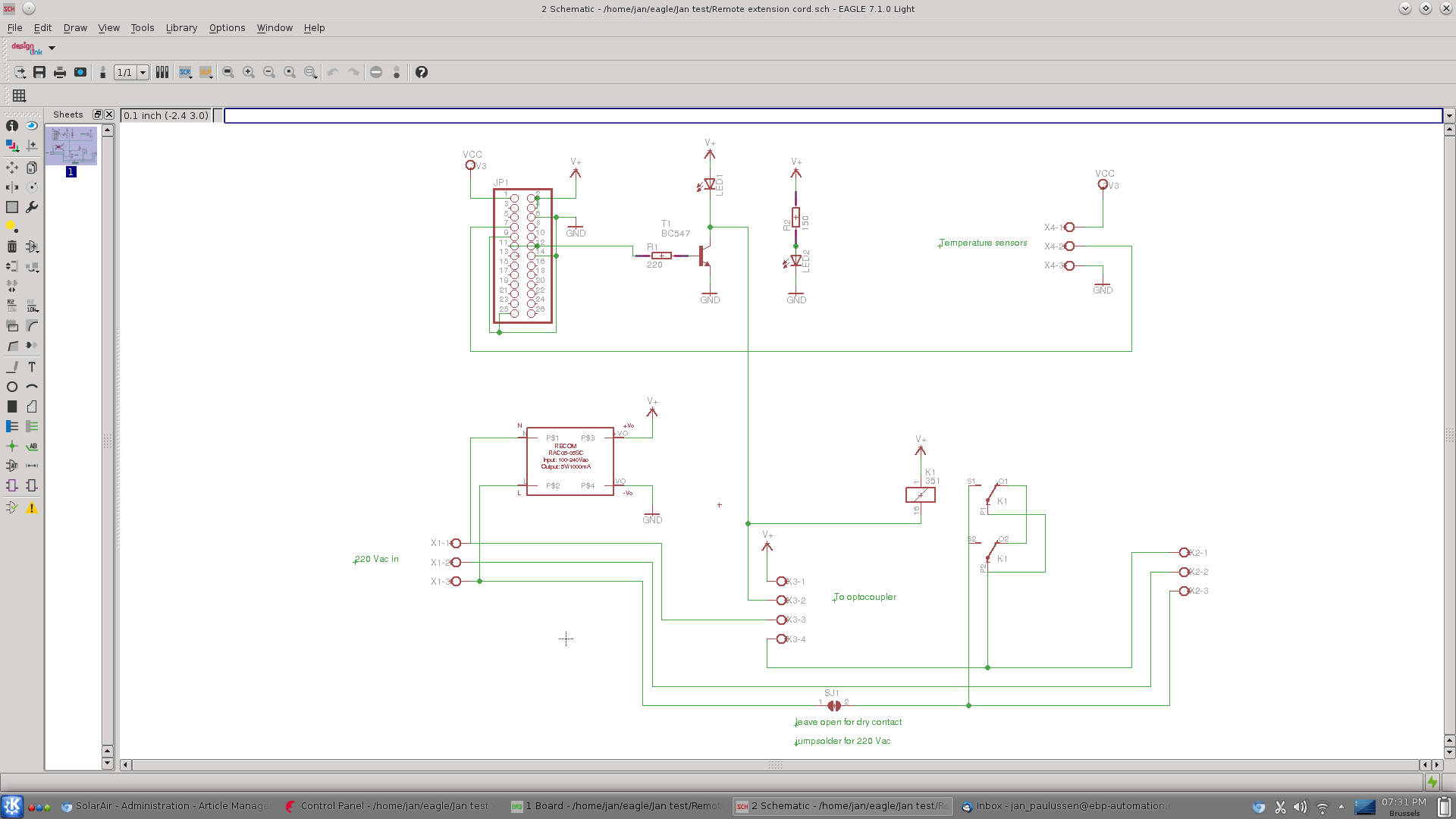
The schematic and PCB have been designed with the Eagle PCB software, that is free for hobbyists.
This is the partlist:
Partlist
Exported from Remote extension cord.sch at 1/5/16 7:57 PM
EAGLE Version 7.1.0 Copyright (c) 1988-2014 CadSoft
Assembly variant:
Part Value Device Package Library Sheet
JP2 PINHD-2X20 2X20 pinhead 1
K1 351 351 351 relay 1
LED1 LED5MM LED5MM adafruit 1
LED2 LED5MM LED5MM adafruit 1
R1 220 R-EU_0207_15 0207/15 resistor 1
R2 150 R-EU_0207_15 0207/15 resistor 1
SJ1 SJW SJW jumper 1
T1 BC547 BC547 TO92 transistor 1
U$1 RAC05-05SC RAC05-05SC RECOM_RAC05-05SC janlib 1
X1 W237-103 W237-103 con-wago-500 1
X2 W237-103 W237-103 con-wago-500 1
X3 W237-4 W237-4 con-wago-500 1
X4 W237-103 W237-103 con-wago-500 1
Here the schematic;
Below the PCB design

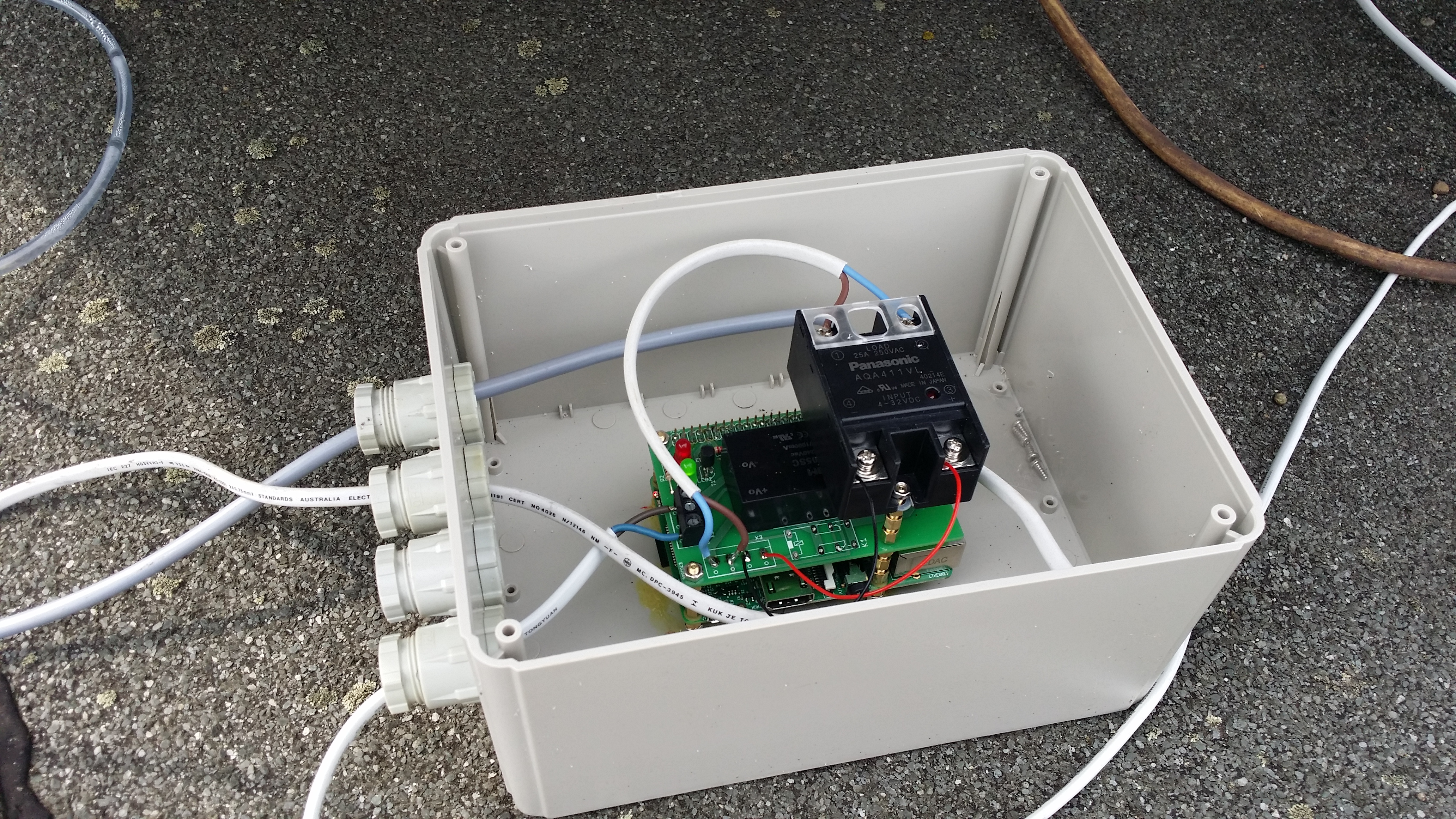
If you then stack this PCB on top of the raspberry, and put the Solid State relais on top, tis is how it looks;
This is how it is built in: